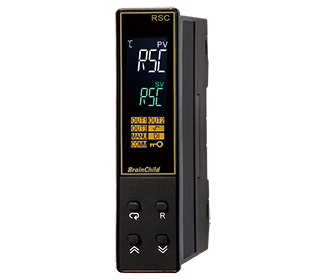
The IA10's high-brightness LCD screen enhances readability, featuring three display sections that can separately show Input 1, Input 2, and the current device status. It is equipped with multiple alarms and event inputs to strengthen on-site equipment's visual control. The IA10 supports a 5-digit display, capable of showing up to 4 decimal places. Additionally, it allows basic addition, subtraction, multiplication, and division operations between Input 1 and Input 2, with the results displayed in Window 1.
The IA10 Indicator and Alarm Unit features 2 input channels, which can undergo basic arithmetic operations. Additionally, for common sensor inputs that may follow non-linear functions, the IA10 can apply up to 11-point correction. The panel includes three LCD displays, with the main and secondary displays capable of showing up to five digits, with support for 4 decimal places. On the left side, there is an area for status indicators and unit displays (℃, ℉, and PU stands for Process Unit). The IA10 includes optional 5 alarms or 3 linear signal retransmission functions, capable of transmitting input signals or computed results. Moreover, it offers 6 event input controls, useful for alarm resetting or other useful control options.
| Power |
|---|
| Power Supply |
90 to 250 VAC, 47 to 63 Hz, 20 to 28 VAC, 47 to 63 Hz / 11 to 40 VDC |
| Power Consumption |
12VA,6W Maximum |
| Over Voltage Category |
II |
| Input 1 |
|---|
| Type |
Thermocouple (J,K,T,E,B,R,S,N,L,U,P,C,D), RTD(PT100(DIN),PT100(JIS)),
Current(mA),Voltage(V,mV) |
| Resolution |
18 Bits |
| Sampling Rate |
5 Times/Sec (200 msec) |
| Input 2 |
|---|
| Type |
Linear Current, Linear Voltage |
| Resolution |
18 Bits |
| Sampling Rate |
0.9 time/Sec |
| Alarm |
|---|
| Relay Type |
Form A |
| Maximum Rating |
2A,240VAC, 200,000 Life cycles for resistive load |
| Alarm Functions |
Hi, Lo, Hi Latch, Lo Latch |
| Communication |
|---|
| Interface |
RS485 |
| Protocol |
Modbus RTU(Slave Mode) |
| Address |
1 to 247 |
| Baud Rate |
2.4KBPS to 115.2KBPS |
| Parity Bit |
None, Even or Odd |
| Stop Bit |
1 or 2 Bits |
| Data Length |
7 or 8 Bits |
| Communication Buffer |
160 Bytes |
| Analog Retransmission |
|---|
| Output Signal |
4-20 mA, 0-20mA, 0-10VDC |
| Resolution |
15 Bits |
| Accuracy |
±0.05% Span ±0.0025%/℃ |
| Load Resistance |
0 to 500Ω for current output, 10KΩ minimum for Voltage Output |
| Output Regulation |
0.01% for full load change |
| Output Setting Time |
0.1Second (stable to 99.9%) |
| Isolation Breakdown |
1000VAC min |
| Integral Linearity Error |
±0.005% of span |
| Temperature Effect |
±0.0025% of span / ℃ |
| Saturation Low |
0mA or 0VDC |
| Saturation High |
22.2mA or 5.55V, 11.1V min |
| Linear Output Range |
0-22.2mA (0-20mA/4-20mA), 0-5.55VDC (0-5VDC,1-5VDC), 0-11.1VDC (0-10VDC) |
| User Interface |
|---|
| Keypad |
4 Keys |
| Display Type |
5-Digit LCD Display |
Program Port
| Program Port |
|---|
| Interface |
Micro USB |
| Communication Function |
Firmware Upgrade |
| Digital Filter |
|---|
| Function |
First Order |
| Time Constant |
0, 0.2, 0.5, 1, 2, 5, 10, 20, 30, 60 Seconds, Programmable |
| Environmental and Physical Specifications |
|---|
| Operatin Temperature |
-10℃ to 50℃ |
| Storage Temperature |
-40℃ to 60℃ |
| Humidity |
0 to 90 % RH (Non-Condensing) |
| Altitude |
2000 Meters Maximum |
| Pollution |
Degree II |
| Insulattion Resistance |
20MΩ Minimum (@500VDC) |
| Dielectric Strength |
2000VAC,50/60 Hz for 1 Minute |
| Vibration Resistance |
10 to 55 Hz, 10m/s2 for 2 Hours |
| Shock Resistance |
200 m/s2(20g) |
| Housing |
Flame Retardant Polycarbonate |
| Mounting |
Panel |
| DIN Size |
1/8 |
| Dimensions (W*H*D)(mm) |
96*48*59 |
| Depth Behind Panel (mm) |
50 |
| Cut Out Dimensions (mm) |
92*45 |
| Weight (grams) |
220 |
| Approval Standards |
|---|
| Safety |
UL 61010-1, 3rd Edition, CAN/CSA-C22.2 No.61010-1(2012-05), 3rd Edition, ROHS, REACH |
| Protective Classs |
IP50 for the front panel, IP20 for rear terminals and housing. All indoor use. |
| EMC |
EN61326 |




.png)
