


.png)
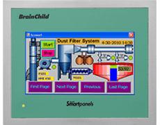
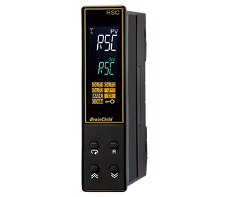
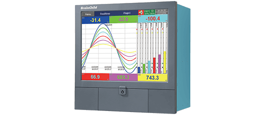
MCT_Multi Loop Controller


Additional files
MCT_Intro._v2.00_EN.pdf- Up to 3 PID loops - 1 may be FM Limit
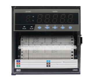
- Paperless recorder/data logger
- Trend viewer/data viewer
- File transfer/backup via LAN/ WAN/Cloud. Configure via USB memory stick or cloud.
- Email on alarm
- Remote access
- NEMA 4X / IP 65
- Math/Logic/Timers
- Up to 8 monitor points

| Technical Specifications | |
|---|---|
| Size | 4.3" |
| Resolution (W X H mm) | 480 x 272 |
| Display type | TFT, Wide Touch Screen |
| Colors | 65,536 |
| Touch screen Type | Resistive analog |
| Active display area (W X H mm) | 95 X 54 |
| MTBF backlight at 25 °C | 30,000 hrs. |
| Backlight | LED |
| Brightness Adjustment | Yes |
| Screen Saver | Yes |
| Language Fonts | Yes |
| Main Hardware | |
|---|---|
| Processor, CPU speed | ARM Cortex-A8, 1Ghz |
| Flash Memory (ROM) | 128 MB |
| SDRAM (RAM) | 256 MB |
| Operating system | WinCE 6.0 |
| Real-Time Clock | Yes |
| Buzzer | Yes |
| SD card slot | Yes |
| Communication Port/ Interfaces | |
|---|---|
| RS232C / RS485, DB9 Male | 1 |
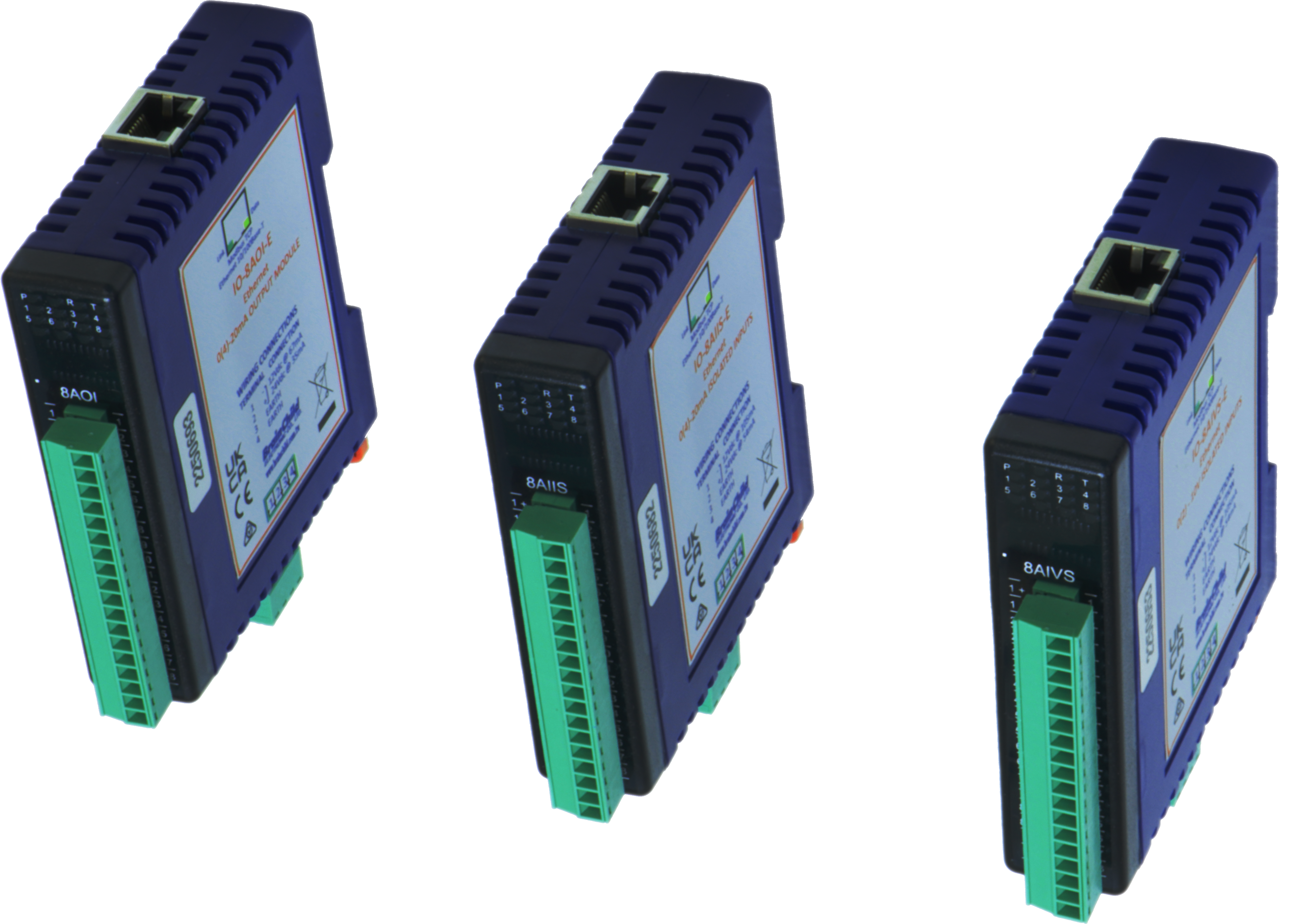
| Ethernet 10/100 Mbps, RJ45 | 1 |
| USB Host | 1 |
| RS485, screw terminal | 1 |
| General Specifications | |
|---|---|
| Rated Voltage | 110/220 VAC (24 VDC) |
| Power supply | 90-250 VAC(11-26VDC) |
| Rated Current | 0.8A AC (3.27A DC) |
| Power Consumption | 36VA (15W) |
| Outer dimensions (W X H X D mm) | 122 X 100 X 134 |
| Mounting depth (mm) | 123 |
| Panel cut (W X H mm) | 92 x 92 |
| Protection | IP66/NEMA 4X front, IP20 housing and terminals |
| Front bezel, housing | Plastic, plastic |
| Installation | Panel Mount |
| Net Weight (Kg) | 0.65 |
| Standards, Certificates and Approvals | |
|---|---|
| UL approval | UL 61010-1 and CSA C22.2 No.61010-1-12 |
| Low Voltage Directive | 2014/35/EU |
| EMC Directive | 2014/30/EU |
| Requirements for Emission | EN 61326-1:2013 |
| Tick mark for Australia | AS/NZS CISPR 11:2004 |
| FCC | FCC Part 15, Subpart B, Class A |
| Base Standards for EMC & Safety | |
|---|---|
| Electrostatic discharge | IEC 61000-4-2: 2008 |
| Radiated radio-frequency electromagnetic fields | IEC 61000-4-3: 2006 + A1:2007 + A2:2010 |
| Electrical fast transient/burst | IEC 61000-4-4: 2012 |
| Surge | IEC 61000-4-5: 2014 |
| Conducted disturbances induced by radiofrequency fields | IEC 61000-4-6: 2014 |
| Power frequency magnetic field | IEC 61000-4-8: 2009 |
| Voltage dips, short interruptions and voltage variations | IEC 61000-4-11: 2004 |
| Emission from Electromagnetic fields | CISPR 11:2009 + A1:2010 Class A |
| Harmonics Current | IEC61000-3-2:2014 |
| Voltage Fluctuation and Flicks | IEC61000-3-3:2013 |
| Requirements for Safety | Requirements for Safety |
| Protective Class | |
|---|---|
| Standard enclosures | IP 66/NEMA 4X (Front), IP20 housing and terminals |
| Operating Conditions | |
|---|---|
| Temperature | 0°C to + 50°C |
| Relative Humidity | 10% to 90%, no condensation |
| Altitude | 2000 meters maximum |
| Pollution | Degree 2 |
| Sinusoidal vibration conforming to IEC 60068-2-6 | 10 to 58Hz: 0.75mm amplitude 58 to 150Hz: 1g 1oct/min. 10 sweeps |
| Shock conforming to IEC 60068-2-29 | 3 shocks per direction 11ms 10g |
NOTE: In temperatures below 0°C, the response time of liquid crystal display becomes slower and color of the display will be darker than normal. Do not operate in ambient temperatures less than 0°C.
| LCD Specifications | |
|---|---|
| Touch operations | 1,000,000 times using R 0.8 Polyacetal stylus with force 250g |
| Vibration test | 10-55 Hz, Stroke: 1.5mm, 2 hrs. for each direction of X, Y, Z |
| Shock test | 100G, 6ms, +/- X, +/- Y, +/- Z, 3 times for each direction |
| Typical viewing angle | Vertical (up/down), 50° / 70° Horizontal (left/right), 70° / 70° |
| Transport & Storage Conditions | |
|---|---|
| Temperature | -20°C to + 60°C |
| Relative Humidity | 10% to 90%, no condensation |
| Altitude | 2000 meters maximum |
| Sinusoidal vibration conforming to IEC60068-2-6 | 5 to 16.8 Hz: 3.5 mm amplitude 16.8 to 150 Hz: 2g 1oct/min. 40 sweeps |
| Shock conforming to IEC 60068-2-29 | 3 shocks per direction 11ms 15g |
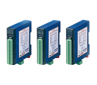
PCM/HLM Module Specifications
| Signal Input | ||||
|---|---|---|---|---|
| Input characteristics | ||||
| Type | Range | Accuracy @ 25°C | Input Impedance | |
| J | -120°C to 1000°C (-184°F to 1,832°F) | ±2°C | 2.2 MΩ | |
| K | -200°C to 1370°C (-328°F to 2498°F) | ±2°C | 2.2 MΩ | |
| T | -250°C to 400°C (-418°F to 752°F) | ±2°C | 2.2 MΩ | |
| E | -100°C to 900°C (-148°F to 1652°F) | ±2°C | 2.2 MΩ | |
| B | 0°C to 1820°C (32°F to 3308°F) | ±2°C( 200°C to 1800°C ) | 2.2 MΩ | |
| R | 0°C to 1767 .8°C (32°F to 3214°F) | ±2°C | 2.2 MΩ | |
| S | 0°C to 1767.8°C (32°F to 3214°F) | ±2°C | 2.2 MΩ | |
| N | -250°C to 1300°C (-418°F to 2372°F) | ±2°C | 2.2 MΩ | |
| L | -200°C to 900°C (-328°F to 1652°F) | ±2°C | 2.2 MΩ | |
| U | -200°C to 600°C (-328°F to 1112°F) | ±2°C | 2.2 MΩ | |
| P | 0°C to 1395°C (32°F to 2543°F) | ±2°C | 2.2 MΩ | |
| C | 0°C to 2300°C (32°F to 4172°F) | ±2°C | 2.2 MΩ | |
| D | 0°C to 2300°C (32°F to 4172°F) | ±2°C | 2.2 MΩ | |
| PT100 (DIN) | -200°C to 850°C (-328°F to 1562°F) | ±0.4°C | 1.3KΩ | |
| PT100 (JIS) | -200°C to 600°C (-328°F to 1112°F) | ±0.4°C | 1.3KΩ | |
| Output Specifications | ||
|---|---|---|
| Relay Rating | 2A/240 VAC, life cycles 200,000 for resistive load | |
| Pulsed Voltage | Source Voltage 5V @30mA, current limiting resistance 66 ohms Source Voltage 14V @40mA, current limited at 70mA | |
| Linear Output (PCM) | Resolution: | 15 bit |
| Output Regulation | 0.02% for full load change | |
| Output Setting Time | 0.1 sec (stable to 99.9%) Isolation | |
| Breakdown Voltage | 1000 VAC | |
| Temperature Effect | +/-0.01% of span per degree C | |
| Analog Retransmission (PCM) | Output Signal | 4-20 mA, 0-20 mA 0-5VDC, 1-5VDC, 0-10VDC |
| Resolution n | 15 bits | |
| Accuracy | +/-0.05% of span +/-0.0025% / C Load |
|
| Resistance | 0-500 ohms (for current output)10K ohms minimum (for voltage output) | |
| Output Regulation | 0.01% for full load change | |
| Output Settling Time | 0.1 sec (stable to 99.9%) | |
| Isolation Breakdown Voltage | 1000 VAC min Integral | |
| Linearity Error | +/-0.005% if span | |
| Temperature Effect | +/-0.0025% of span per degree C | |
| Saturation Low | 0 mA (or 0 VDC) | |
| Saturation High | 22.2 mA (or 5.55VDC, 11.1 VDC min) | |
| Linear Output Range | 0-22.2 mA (0-20 mA or 4-20 mA) | |
| Volts DC | 0-5.55 VDC (0-5VDC, 1-5VDC)0-11.1 VDC (0-10VDC) | |
| General Specifications | |
|---|---|
| Resolution | 18 Bits |
| Sampling rate | 5 Times / Second (200msec) |
| Maximum rating | -2VDC minimum, 12VDC maximum |
| Temperature effect | 1.5µV /°C for all inputs except mA input, 3.0µV /°C for mA |
| Sensor lead resistance effect | Thermocouple: 0.2 µV /Ω; 3-wire RTD: 2.6°C /Ω of Difference of Resistance of two leads 2-wire RTD: 2.6°C /Ω of Sum of Resistance of two leads |
| Burn-out current | 200nA |
| Common mode rejection ratio(CMRR) | 120 dB |
| Normal mode rejection ratio (NMRR) | 55 dB |
| Sensor break detection | Sensor open for Thermocouple and RTD inputs, sensor short for RTD input, below 1mA for 4-20mA input, below 0.25V for 1-5V input, not available for other inputs |
| Electrical Isolation | Optical isolation; 1500V~ (ac) minimum, between input signals and power supply circuit |
| Control Function (PCM) | ||
|---|---|---|
| Control Action | Direct and Reverse | |
| Proportional Band | Temperature | 0.1 to 500°C (0.1 to 900°F) |
| Linear Input | 0.1 to 900.0 | |
| Reset (Auto) | 0 to 3600 seconds | |
| PB Offset | 0 to 100% | |
| Dual PID Heat/ Cool (bimodal) | Cool Proportional Band | 50 to 300% of heat PB |
| Proportional Deadband | -36.0% to +36.0% of heat PB | |
| Time Proportioning Cycle Time | 0.1 to 90 seconds | |
| On-Off/ Alarm Hysteresis (PCM/HLM) | 0.1 to 50°C (0.1 to 90°F) | |
| Event Input Specifications | |
|---|---|
| Logic Low | -10V minimum, 0.8V maximum |
| Logic High | 2V minimum, 10V maximum |
| Approval Standards | |
|---|---|
| UL/ cUL | UL 61010C-1 |
| EN | EN 61010-1 (IRC1010-1) |
| EMC | EN61326 |
| RoHS | RoHS 2.0 Compliant, WEEE |
| FM (HLM) | FM temperature limit switch – indicating |
| □ | □ | □ | □ | □ |
| 1 | 2 | 3 | 4 | 5 |
|
1 Power Input |
4: 90-250VAC 50/60Hz 5: 11-26VAC/DC |
|
2 Module Type Slot 1 |
0: None |
|
3 Module Type Slot 2 |
0: None |
|
4 Module Type Slot 3 |
0: None |
|
5 Special Order Code |
000: None |
Note
- PCM Modules can be installed in slots 1, 2 or 3
- Select PCM and HLM Ordering code for slot 1 to 3
| □ | □ | □ | □ |
| 1 | 2 | 3 | 4 |
|
1 Output 1 |
0: None |
|
2 Output 2 |
0: None |
|
3 Output 3 |
0: None |
|
4 Output 4 |
0: None |
Note
- PCM Modules can be installed in slots 1, 2 or 3
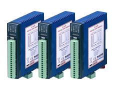
- PCM Modules support Universal Analog Signal Inputs T/C-RTD, mA, and VDC
- Hardware configuration is via board DIP switch
- Default hardware configuration is T/C-RTD
| □ | □ | □ |
| 1 | 2 | 3 |
|
1 Singal Input |
1: Thermocouple: J, K, T, E, B, R, S, N, L, C, P,PT100 DIN, PT100 JIS, 0-60mV |
|
2 Output 1 |
0: None |
|
3 Output 2 |
0: None |
Note
- HLM Modules can be installed in slots 2 with loop system or 3 with loop system
- Hardware configuration for each input type is via board Dip switch.
- HLM signal input ordering code #1 Support Universal Analog Inputs Thermocouple, RTD, 0-10VDC, 4-20mA / 0-20mA
- HLM configured with Signal inputs 0-60mV,0-1VDC, 0-5VDC,0-10VDC ,0-20mA and 4-20mA are not FM approved